Day 02 - Entering 32bit Protected Mode
Yesterday, we wrote a program that automatically boots up and prints “Hello World” on the screen. As you may noticed, we are interacting with CPU in 16-bit mode. Nowadays, most processers are 64-bit processors. We need to be updated. So, today, we are going to enter 32 bit mode.
Here are the download links to files that is mentioned in today’s work.
Basic Knowledge
Real and Protected Mode
By default, when the processor is powered up, it first operates in 16 bits mode. This is a routine followed by both processers and OS. As a result, you will see a large portion of today’s code similar to yesterday’s code. Then, by running some initializing program, we “upgrade” the processor to work in 32 bit mode. For 32 bit mode, there are Real mode and Protected mode. Real mode means you need to control Interruptions by yourself. For a corresponding assembly code, you will see a lot of “int 0x3” inside. Protected mode means the interruptions are protected by processors. Your I/O messages go first into buffers and the system decide when to call interrupts. Since protected mode has a lot of benefits, we’ll follow that.
A20 Line
Before entering the 32 bit mode, we need to enable something called A20 line. Here is the story. For 8086, 80186 processors, there are 20 address lines ranging from A0 to A19. With 20 address lines, the processor can accessing 0 ~ \(2^{20}-1\) Bytes, in all 1 MB. However, the internal address register, a register that stores the actual memory address, can only handle 16 bit addresses. As a result, in order to handle 20 bit addresses, one 4-bit register needs to be involved. However, there is no 4-bit registers in the processor. Finally, engineers decided to use another 16 bit segment register. The final rule to generate the actual address is:
where both segment and offset are 16-bit.
E.g.
For \(segment = 0xF800\) and \(offset=0x0001\), the actual address is \(0xF800 << 4 + 0x0001 = 0xF8001\).
But, it’s possible for a programmer to indicate an address larger than 1MB, say \(0xFFFF << 4 + 0x0011 = 0x100001\) refers to an address larger than 1MB. If there is no address 20 line, \(0x100001\) is equivalent to \(0x00001\). If we enable A20, \(0x100001\) mean the second byte beyond 1MB. This is a must if the memory is larger than 1MB.
GDT
Since we have larger memory, we want to organize them better. GDT (Global Descriptor Table) is a structure that marks some information about a segment of memory. In general, code and data are stored at different segments in the memory. The GDT indicates where the code and data segments are, how large, and some other parameters. A more detailed explanation will be in Day 06’s code. Let’s ignore this concept temporarily.
VGA Mode
A screen can be configured in Graphic or Text mode, each pixel can have 1-bit, 4-bit, 8-bits color parameter, the resolution can be 80x25, 320x200, etc. All these mode are configured in VGA Mode. A more detailed list of VGA modes can be found in VGA Modes .
Today’s code only deal with texts, so we configure vga to be mode 0x03, which is 16-bit color, each charactor (not pixel) is of 9x16 pixel and the whole screen can display 80x25 charactors.
Source Code
; initial 16 bit boot code
bits 16
org 0x7c00

boot:
    ; enable A20 bit
    mov ax, 0x2401
    int 0x15

    ; set vga to be normal mode
    mov ax, 0x3
    int 0x10

    cli                                     ; Clear interrupt flag;
    lgdt [gdt_pointer]              ; Load Global/Interrupt Descriptor Table Register

    mov eax, cr0                    ; CR0 has various control flags that modify the basic operation of the processor
    or eax,0x1                              ; EAX |= 0x01 set the protected mode bit on special CPU reg cr0
    mov cr0, eax                    ;
    jmp CODE_SEG:boot2              ; jump to CODE_SEG boot2
gdt_start:
    dq 0x0
gdt_code:
    dw 0xFFFF
    dw 0x0
    db 0x0
    db 10011010b
    db 11001111b
    db 0x0
gdt_data:
    dw 0xFFFF
    dw 0x0
    db 0x0
    db 10010010b
    db 11001111b
    db 0x0
gdt_end:
gdt_pointer:
    dw gdt_end - gdt_start-1
    dd gdt_start

CODE_SEG equ gdt_code - gdt_start
DATA_SEG equ gdt_data - gdt_start

bits 32

boot2:
    ; now, initial stack to data segment
    mov ax, DATA_SEG
    mov ds, ax
    mov es, ax
    mov fs, ax
    mov gs, ax
    mov ss, ax
    mov esi,hello
    mov ebx,0xb8000

; Note that, since we are in protected mode, we cannot call BIOS INT any more.
; Instead, we feed ASCII to buffer, which is [ebx]
.loop:
    lodsb                           ; load string byte from [DS:SI] into AL
    or al,al                        ;
    jz halt                         ; the above two lines => jump if AL==0. Equivalent to CMP AL; JE halt
    or eax,0x0100           ; config text color to be 1 (blue)  [4bit bg color][4bit text color][8bit ascii]
                        ; more color info can be found in https://en.wikipedia.org/wiki/Video_Graphics_Array#Color_palette
    mov word [ebx], ax      ; feed ASCII and color to buffer in memory
    add ebx,2                       ; increase ebx by two bytes (1byte for color, 1byte for ASCII)
    jmp .loop
halt:
    cli
    hlt
hello: db "Hello world!",0

times 510 - ($-$$) db 0
dw 0xaa55
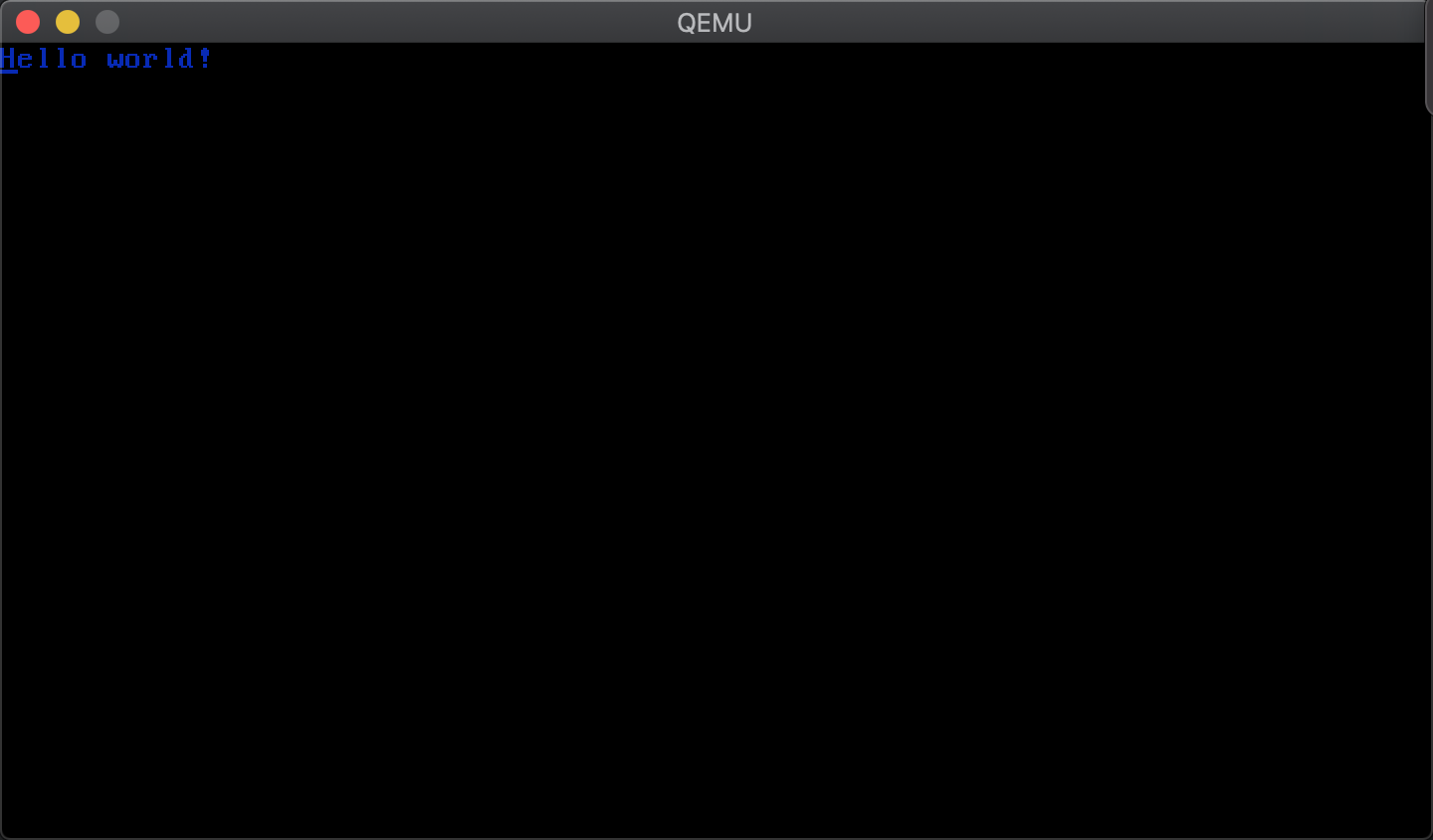
Result
Execute make run you will see